RK Singh Raman*
Department of Mechanical and Aerospace Engineering, and Department of Chemical Engineering, Monash University (Melbourne), Vic 3800, Australia
*Corresponding Author. Email: This email address is being protected from spambots. You need JavaScript enabled to view it.
Frontier Research Today, 2018, 1:1003
Published Online: 02 November 2018 (Review)
DOI: 10.31716/frt.201801003
Abstract
This article reviews two reasonably novel approaches for remarkable corrosion resistance of metallic material, and discusses challenges and future opportunities. In the first approach, the nanaocrystalline structure of a corrosion resistant alloy has been found to bring about remarkable improvement in oxidation/corrosion resistance of alloys, as a result of the enhancement in diffusivity of the alloying element that is responsible for theformation of a corrosion barrier layer of protective oxide, due to the nanocrystalline structure (vis-à-vis the microcrystalline counterpart of the same alloy). In the second approach, just a monolayer or a few atomic layer thick graphene coating was found to improve corrosion resistance of copper, nickel and copper nickel alloys in aggressive chloride solution by up to two orders of magnitude, because of the unique characteristics of graphene, i.e., impermeability and inertness to aggressive fluids.
Keywords
Nanocrystalline Fe-Cr alloys; Graphene; Corrosion and oxidation resistance
1. Introduction
Corrosion of engineering alloys and its mitigation measures cost any developed economy ~4% of their GDP (i.e., >$250b annually to USA and >$8b to Australia). Therefore, there are always investigations for finding more effective mitigation measures to counter corrosion. However, given the age-old and vexing nature of corrosion, it is often a great challenge to come up with a novel and disruptive measure. Development of corrosion-resistant alloys and application of coatings are among the most common measures to mitigate corrosion. This article reviews relatively novel findings to corrosion resistance through each of the two approaches, i.e., corrosion/oxidation resistance due to nanocrystalline structure of alloys, and due to ultra-thin graphene coatings.
2. Nanocrystalline Alloy Structure for Oxidation/Corrosion Resistance
Nanocrystalline metallic materials have grain size <100 nm. Synthesis and structure of nanocrystalline metals and alloys, and the effect of nanocrystalline structure on the physical and mechanical properties of have been extensively investigated.1-5 There have also been investigations on oxidation and corrosion resistance of nanocrystalline metallic materials, though such studies have not been as extensive. Grain boundaries are high energy areas, and hence, a simplistic approach would suggest a greater corrosion rate of metals and alloys in their nanocrystalline state (than in their microcrystalline counterparts), since the nanocrystalline structures possess much larger fraction of grain boundaries. Indeed, dissolution rate of nanocrystalline copper in a corrosive medium is found to be greater than the conventional microcrystalline copper. However, depending on the alloy/metal-environment system and the type of corrosion, the effect of nanocrystalline structure on corrosion resistance has been found to be both detrimental and advantageous. For example, nanocrystalline structure is reported to cause considerable improvement in oxidation resistance of iron-chromium alloys (as opposed the microcrystalline state of the same alloy), whereas the dissolution rate of copper was found to be greater in nanocrystalline, as described earlier.
Diffusion through grain boundaries is much greater than through the lattice, however, this effect is more pronounced in the low temperature regime. Nanocrystalline metals and alloys have considerably higher volume fraction of grain boundaries (than their microcrystalline counterparts). As a result, those corrosion types that are governed by diffusion in metallic materials (such as high temperature oxidation) can be highly influenced by the nanocrystalline structure. However, whether the predominantly diffusing species has beneficial or detrimental effect will actually govern the nature of the role of the nanocrystalline structure in oxidation/corrosion of the alloy. For example, because phosphorus has a detrimental role in corrosion, a nanocrystalline Ni-P alloy was found corrode at a considerably greater rate than the microcrystalline alloy of same composition.6 On the other hand, when the predominantly diffusing element forms a protective surface film, the nanocrystalline structure facilitates such film formation, and hence, the nanocrystalline alloy will possess superior oxidation/corrosion resistance. Accordingly, nanocrystalline (nc) iron-aluminide and a NC FeBSi alloy were found to possess superior oxidation resistance than their microcrystalline counterparts.7,8 Because Al and Si, the predominantly diffusing species in the respective alloys are also the well-known protective oxide film formers, the nanostructure accelerated early formation of their protective films of Al/Si oxides. Build-up of such beneficial elements at surface to their critical amounts is required for the establishment of a continuous protective layer of oxide, which is governed directly by the rate of their transport to surface, which, in turn, is governed by the alloy grain size, along with other factors, such as temperature, concentration of such element in the alloy and the partial pressure of the oxidizing component.
2.1 Oxidation resistance of nanocrystalline Fe-Cr alloys
As established earlier, a decrease in grain size will facilitate protective film formation, for an alloy where the predominantly diffusing species can form a protective film and provide oxidation resistance. Stainless steels (alloys of iron, sufficient amounts of chromium, and generally, sufficient amounts of nickel) are among the most commonly used corrosion resistant alloys. During oxidation, stainless steels form an outer layer of iron oxide (Fe2O3), and an inner layer of a mixed oxide of iron and nickel. With the Cr supply from the subsurface, the inner layer of Fe-Ni oxide converts into Cr2O3 which is protective for oxidation/corrosion resistance.9 The time taken for transition of Fe-Ni oxide layer into the layer of protective Cr2O3 depends essentially on the rate of outward diffusion of chromium in the alloy matrix. As described earlier, alloy grain size is one the parameters that governs the outward chromium diffusion. The profound dependence of establishment of Cr2O3 layer on alloy grain size during high temperature oxidation has been systematically demonstrated for a specific stainless steel (SS).10 The SS alloy with fine grain size (<17 mm) easily developed a uniform protective layer of Cr2O3, whereas, the same alloy with grain size >40 mm failed to develop the inner layer of Cr2O3 because coarse grain alloy allowed insufficient diffusion through grain boundaries and hence, inadequate chromium supply for establishment of Cr2O3 layer (instead, an inner layer of (Fe,Cr)3O4 continued to grow in the case of the coarse grain alloy).
The extremely fine grain size of nanocrystalline (nc) materials provides high volume fraction of grain boundaries1-5 and an extraordinarily high diffusivity. In fact, Wang et.al11 reported Cr diffusivity in a nanocrystalline Fe-Cr alloy to be nearly four orders of magnitude greater than that in its microcrystalline counterpart at 380 oC. However, when Cr content of the alloy is too low, the grain boundary diffusion of Cr in such low-Cr alloys (e.g., 2.25Cr-1Mo steel) is never enough to allow formation of a contiguous protective layer of Cr2O3.12-15 In fact, in the absence of the protective Cr2O3, a decrease in grain size only provides greater sites for grain boundary oxidation, and thereby, decreases the alloy’s oxidation resistance.14,15
As soundly established in earlier discussion, accumulation of Cr due to grain boundary diffusion will be extraordinarily high in the case of nanocrystalline alloy. On this basis, a nanocrystalline Fe-Cr alloy (with sufficient Cr) should possess considerably superior oxidation resistance than its microcrystalline counterpart. On the same basis, the author hypothesized that it should be possible to for a nanocrystalline Fe-Cr alloy with much lower Cr content (such as just 10% or less Cr content) to possess an oxidation resistance that may be comparable to microcrystalline stainless steels (that contain 18-20% Cr). The author’s group has successfully validated this hypothesis, as described subsequently.
For validation of the hypothesis, nanocrystalline powder of Fe-10%Cr alloy was prepared by ball milling of microcrystalline powders of Fe and Cr, and then the nanocrystalline alloy powder was consolidated into discs.5 Ref. 5 describes the challenges at the different steps of powder processing and consolidation, and their systematic circumvention. As also described in Ref. 5, employing a technique that is based on the X-ray peak broadening, for grain size was determined at various stages of processing. The final grain size was determined to be 52 nm (± 4 nm).5
For investigation into oxidation resistance of nanocrystalline (nc) vis-à-vis microcrystalline (mc) grain sized Fe-10%Cr alloy, a few of the nanocrystalline alloy discs that were synthesized as described above were allowed to undergo grain coarsening into microcrystalline regime (grain size, 1.5 mm), by heating at sufficiently high temperatures for the required duration. The compacted and sintered discs of nc and mc Fe-10wt%Cr alloy were oxidised in air at 300 oC16 (since at 300-400 oC, the grain boundary diffusion vastly predominates the lattice diffusion).11 As seen from Figure 1, nc alloy oxidized at a considerably slower rate than the mc alloy, and after >3000 min, weight gain of nc alloy was found to be nearly an order of magnitude smaller than that the mc alloy. In fact, after the nc alloy suffered somewhat rapid oxidation in the initial stage (240 min), its weight gain was insignificant during subsequent oxidation. The remarkable difference in weight gain (i.e., oxidation resistance) of nc and mc alloys originated from considerably greater Cr content in the inner layer oxide scale developed on the nc alloy, which is evident from the Cr depth profiles by secondary ion mass spectrometry (SIMS) of the oxide scales developed on nc and mc alloys in 30 min of oxidation.17
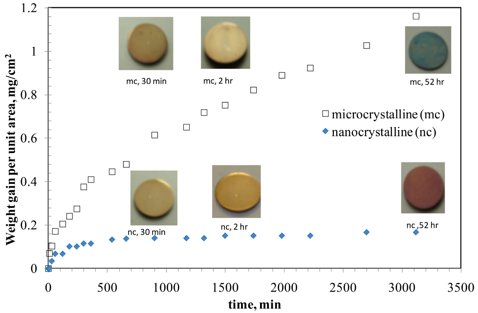
Figure 1. Oxidation kinetics of nanocrystalline (nc) and microcrystalline (mc) Fe-10%Cr alloys, oxidised at 300oC. Reprinted with permission from Ref. 16. Copyright 2010 Taylor & Francis.
The chemistry and Cr content of the thin inner oxide scale that develop on Fe-Cr alloys govern an alloy’s oxidation resistance. Consistent with the weight gain data (Figure 1), SIMS depth profiles for Cr and O suggest the development of a considerably thicker oxide film on mc Fe-10Cr alloy (Figures 2a and 2b). More importantly, as suggested by the Cr peak heights, the Cr content of the inner layer of nc Fe-10Cr alloy is > 4 times higher than that of mc Fe-10Cr alloy, which readily explains the considerably greater oxidation rate of microcrystalline Fe-10Cr alloy Than the nc alloy). Because of its considerably high Cr content, the inner oxide layer was assumed to be of Cr2O3. Further work showed that indeed, the Cr content of the inner layer was in the same regime as that of the oxide layer developed on a stainless steel, establishing that it is possible to develop a protective layer of Cr2O3 in the case of nanocrystalline Fe-Cr alloys at much lower chromium contents (than in conventional stainless steels).16
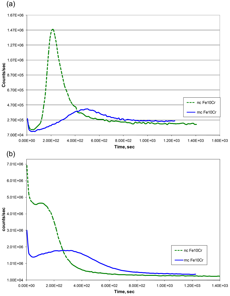
Figure 2. SIMS depth profile for samples of Fe-10%Cr nanocrystalline (nc) and microcrystalline (mc) alloy oxidized for 30min, using Cs+ primary beam: (a) Cr and (b) O. Reprinted with permission from ref 17. Copyright 2009 Elsevier.
As seen in Figure 1, at the end of the oxidation test, the colours of the oxidised nc and mc Fe-Cr alloy were distinctly different (red and greenish blue respectively). Again, this can be explained on the basis of the development of a highly protective layer of Cr2O3 on the nc alloy. It takes some time for sufficient Cr to segregate in the inner layer for the Fr-Cr mixed layer to transform into a well-established Cr2O3 layer. As seen in Figure 1, in the initial stage, nc alloy oxidized at somewhat rapid rate, and the resulting oxide is predominantly Fe-rich (Fe3O4) that allowed considerable outward diffusion of Fe, until the inner layer of Cr2O3 gradually established. With the establishment of Cr2O3 layer, the outward diffusion of Fe subsides considerably. In the absence of Fe supply, the outer layer Fe3O4 that had formed earlier gets oxidsed into Fe2O3 (which has a red appearance, i.e., the colour of the nc alloy oxidized for >3100 h).
The discussion of oxidation kinetics and SIMS depth profile results (Figures 1 and 2) has enabled the validation of the hypothesis that a nanocrystalline Fe-Cr alloy with sufficient Cr possesses considerably superior oxidation resistance than its microcrystalline counterpart. Further, it was also established that with nanocrystalline structure and much lower Cr content, it is possible to develop oxidation resistance as good as that of the common high chromium microcrystalline Fe-Cr alloys (stainless steels).16
2.2 Further opportunities for oxidation resistance due nanocrystalline structure
Oxidation resistant alloys possess Cr, Si and/or Al in sufficient amount to develop a protective layer of oxide of one or more of these mandatory alloying elements. Oxidation resistance of the alloys that are capable of developing Al-oxide layer is much superior to the oxidation resistance of alloys that develop Cr-oxide layer (such as common stainless steels). However, the Al content required in a Fe-Al microcrystalline alloy for establishing a complete layer of Al-oxide renders the alloy unacceptably brittle. To circumvent this problem, instead of Fe-Al alloy with the required Al content for developing Al-oxide layer, Fe-Cr-Al microcrystalline alloys are used where the “third element effect”18 of Cr enables formation of a complete layer of Al-oxide at a much lower Al content (thereby, avoiding the problem of brittleness). Because of their considerably greater Fe and Cr contents than Al, such Fe-Cr-Al microcrystalline alloys quickly develops a complete layer of Cr2O3, which retards/stops diffusion of Fe, Cr, Al and oxygen. Since Al is not able to diffuse outward beyond Cr2O3 layer, it enriches underneath Cr2O3 layer, and eventually enables formation of a complete layer of Al2O3 immediately underneath the Cr2O3 layer. This role of Cr in facilitating Al2O3 layer formation is called the “third element effect”18,19. On the basis of the profound role of nanocrystallinity of an alloy in facilitating formation of protective oxide layer, as established in Section 2.1 above, it may be possible to accelerate the formation of Al2O3 layer of Fe-Cr-Al alloys (possibly at a still lower Al content) if the alloy’s grain size were to be in the nanocrystalline regime. Furthermore, nanocrystalline structure will also facilitate accelerated development of Cr2O3 layer, which is a prerequisite for the development of a complete Al2O3 layer at much lower Al content.
3. Graphene Coating for Remarkable Corrosion Resistance
Graphene research was awarded a Nobel Prize in 201020. Graphene is a honeycomb network of carbon atoms (Figure 3a).21 Graphene possesses extraordinary properties, such as a unique combination of high strength and high ductility.21 Graphene also possesses exceptional properties that may qualify it to be an ideal coating material for corrosion resistance, such as it is inert to even most aggressive chemicals (e.g., HF). The geometric pore size of the honeycomb network of sp2 hybridized carbon atoms in graphene is 0.064 nm.22 Hence, the graphene layer on metals should theoretically provide an ideal impermeable barrier even to the smallest molecules such as He,23 and therefore, it should effectively prevent the aggressive corrosive agents from reaching the substrate underneath for very long periods.
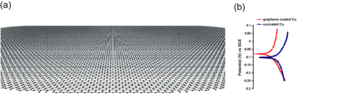
Figure 3. (a) Schematic diagram of a graphene sheet (Ref. 20), and (b) Bode plots confirming the graphene coated Cu (Ref. 25) to have ~2 orders of magnitude superior corrosion resistance in sea water than the uncoated Cu (Note, the magnitude of |Z| (on the y-axis) at the lowest frequencies represents corrosion resistance).
An ideal surface barrier coating for corrosion resistance: (a) should be resistant/immune to chemical degradation due to in aggressive environment, (b) should not allow transport of corrosive fluid, and (c) should possess a good combination of both strength and ductility (i.e., toughness) for mechanical integrity of the coating. While several other materials may possess one or other of these properties, graphene is possibly the only material that possesses all these characteristics. For example, ceramics and graphite may be chemically immune, but as they are very brittle, they can easily break, they have not been extensive used as coatings. On the other hand, polymeric coatings may be flexible, but they can degrade due to ultraviolet radiation and aggressive chemicals such as alkalis. In contrast, graphene, as described earlier, possesses an excellent combination of strength and ductility (i.e., toughness), is chemically quite inertness and is extraordinarily impermeable. Hence, graphene was heralded as ‘the thinnest known corrosion-protecting coating.24 In fact, the author’s group has demonstrated an atomically thin graphene layer deposited on copper substrate to improve corrosion resistance of the metal by nearly 100 times in an aggressive chloride solution similar to sea-water, as shown in Figure 3b.25 The disruptive approach of ultra-thin graphene coating for extraordinary corrosion resistance is commercially immensely valuable, since corrosion is an age-old, vexing and extremely expensive phenomenon, as described earlier.
In a stark contrast to the excellent corrosion barrier property of graphene, as described earlier,25a subsequent report26 bears the title, ‘Graphene as a Long-Term Metal Oxidation Barrier: Worse than Nothing’, i.e., the graphene coating in this study26 was found to drastically deteriorate corrosion resistance of copper. In fact, graphene coatings on copper have been reported to provide different degrees of improvement in corrosion resistance in the first three studies on this topic24,25,27 (i.e., from >2 orders of magnitude,25 to only 10 times25 to little improvement27), as shown through the potentiodynamic polarization plots in Figure 4. Such variability in the ability of graphene to provide corrosion resistance arises from the nature and defect contents of the graphene coatings in these studies.
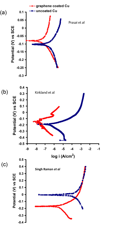
Figure 4. Improvement in corrosion resistance (i.e., decrease in anodic current density) due to graphene coating on Cu, reported in the studies by Prasai et al (Ref. 24), Kirkland et al (Ref. 27) and Singh Raman et al (Ref. 25).
3.1 Role of defects in graphene’s performance as corrosion resistant coating
In reality, graphene deposited on metal can consist of different types of defects, such as graphene domain boundaries and wrinkles. These defects in graphene films profoundly influence the corrosion resistance of the graphene coated metals. For example, the gaps at the inter-domain boundaries of graphene can allow easy access of corroding species to the underlying metal. In Chen et al’s report28 the narrow gaps at the graphene domain boundaries can be seen to exclusively develop oxide when exposed to high temperature air (Figure 5). One of striking findings on the role of these defects is by Prasai et al24 on corrosion resistance of graphene coated Ni samples that were produced by two different routes. The coatings developed by chemical vapour deposition (CVD) process provided improvement by 10 times whereas those developed by mechanically transferring two or four layers of graphene onto Ni substrates resulted in a maximum improvement by only 4 times (Figure 6). It is extremely important to reiterate that during CVD, graphene film on Ni develops by the combined mechanism of a surface catalysis, and a greater solubility of carbon in Ni at high temperatures and rejection of carbon from the metal matrix during cooling allows formation thin surface layer(s) of graphene29,30. The graphene coating thus developed has a good adhesion with the substrate, as well as, possibly, has a good surface coverage and less defects, which explains the superior corrosion resistance due to CVD graphene coating (as opposed to the coating of mechanically transferred graphene layers on Ni)24. But, the graphene coatings developed by mechanically transferring the layers of graphene onto Ni apparently had channels/discontinuities that allowed ion transport, and hence provided only up to 4 times improvement in corrosion (Figure 6)24.
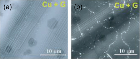
Figure 5. SEM images of graphene coated Cu (a) before and (b) after exposure to air at 200oC for 4 h (Ref. 28) (showing oxide formed at graphene domain boundaries).
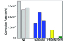
Figure 6. Corrosion rate: GrNi corresponds to graphene coating on Ni by CVD, and tr2Gr/Ni and tr4Gr/Ni respectively represent mechanically transferred 2 and 4 graphene layers onto Ni, and Ni is uncoated-Ni. Reprinted with permission from ref 24. Copyright 2012 American Chemical Society.
The profound influence of the defects and discontinuities in graphene coatings also explains the different degrees of improvement in aqueous corrosion resistance of Cu due to graphene coating used in different studies (Figure 4). Shriver et al26 have demonstrated graphene coated copper to show remarkably inferior oxidation resistance than bare copper during long-term oxidation in air at 185-250 oC. Such variations primarily arose from the quality of graphene films, i.e., irregularities / lack of complete coverage and cracks in the graphene films. Shriver et al26 have categorically attributed the long-term deleterious role of the coating to the poor coverage at the boundaries of graphene domains and high charge conductivity of graphene. It is emphasised that the discontinuities in graphene coatings are particularly effective in electrochemically accelerating corrosion because graphene/graphite is highly cathodic which will force the anodic sites of metal substrate to corrode rapidly, as suggested in the author’s report25.
3.2 Circumventing defect-assisted corrosion acceleration due to graphene coating
In the light of the deleterious effect of discontinuities and defects in accelerating corrosion, as described above, it becomes necessary to achieve complete surface coverage of graphene for a durable corrosion resistance due to graphene coating. Author’s group hypothesize that a multilayer graphene (instead of single layer graphene) may be able to provide an effective surface coverage, as schematically shown in Figure 731. They subsequently validated this hypothesis by experimentally demonstrating multilayer graphene coating to provide considerably durable corrosion resistance to copper31.
Further, by tailoring graphene deposition parameters32, author’s group has considerably succeeded in circumventing the factors that contributed to the development of deleterious defects in graphene film that trigger accelerated corrosion. The multilayer graphene with less defect contents thus developed in the author’s most recent study32 has been demonstrated to provided durable corrosion resistance to nickel, as seen in Figures 8 and 9.32
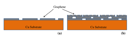
Figure 7. Schematics of: (a) single layer graphene with bare locations at the graphene domain boundaries, (b) multilayer graphene with the graphene domain boundaries of inner layer masked by the immediately upper layer (Ref. 31).
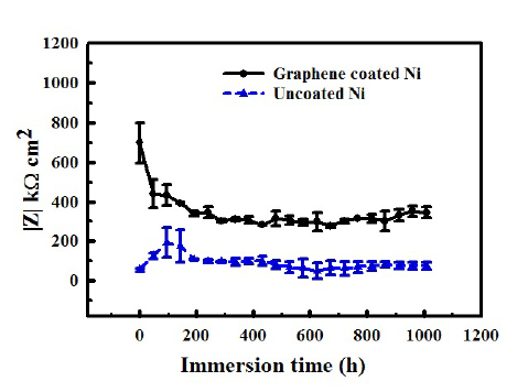
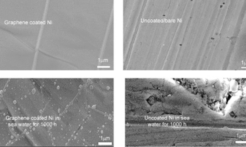
Figure 8. Impedance (|Z|) vs immersion time plots showing the graphene developed on nickel under the optimized condition provided durable corrosion resistance in sea water for >1000 h (plots redrawn from data in Ref. 32). Note: the magnitude of |Z| on the y-axis) is a measure of corrosion resistance. Reprinted with permission from Ref 32. Copyright 2018 Elsevier.
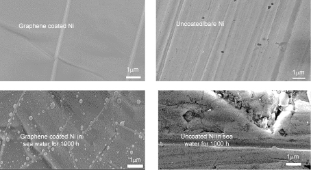
Figure 9. Unlike uncoated Ni (that suffered pitting and corrosion), the graphene coated Ni suffered little (invisible) pitting and corrosion. Reprinted with permission from Ref. 32. Copyright 2018 Elsevier.
4. Conclusions
This review has established successful application of two approaches of nanotechnology in achieving remarkable corrosion resistance, i.e., due to graphene coating, and incorporation of nanaocrystalline structure of an alloy. While this article reviews current status of research and development on the two topics, it also provides a description of the opportunities.
Notes
The authors declare no competing financial interest.
References
[1] Cheng S, Ma E, Wang Y, Kecskes L, Youssef K, Koch C, et al. Tensile properties of in situ consolidated nanocrystalline Cu. Acta Materialia. 2005;53(5):1521–33. doi: 10.1016/j.actamat.2004.12.005
[2] Youssef KM, Scattergood RO, Murty KL, Horton JA, Koch CC. Ultrahigh strength and high ductility of bulk nanocrystalline copper. Applied Physics Letters. AIP Publishing; 2005;87(9):091904. doi: 10.1063/1.2034122
[3] Youssef KM, Scattergood RO, Murty KL, Koch CC. Nanocrystalline Al–Mg alloy with ultrahigh strength and good ductility. Scripta Materialia. 2006;54(2):251–6. doi: 10.1016/j.scriptamat.2005.09.028
[4] Malow TR, Koch CC. Mechanical properties, ductility, and grain size of nanocrystalline iron produced by mechanical attrition. Metallurgical and Materials Transactions A. 1998;29(9):2285–95. doi: 10.1007/s11661-998-0106-1
[5] Gupta R, Singh Raman RK, Koch CC. Grain growth behaviour and consolidation of ball-milled nanocrystalline Fe–10Cr alloy. Materials Science and Engineering: A. 2008;494(1-2):253–6. doi: 10.1016/j.msea.2008.04.019
[6] Rofagha R, Erb U, Ostrander D, Palumbo G, Aust KT. The effects of grain size and phosphorus on the corrosion of nanocrystalline Ni-P alloys. Nanostructured Materials. 1993;2(1):1–10. doi: 10.1016/0965-9773(93)90044-c
[7] Tong HY, Shi FG, Lavernia EJ. Enhanced oxidation resistance of nanocrystalline FeBSi materials. Scripta Metallurgica et Materialia. 1995;32(4):511–6. doi: 10.1016/0956-716x(95)90829-9
[8] El Kedim O, Paris S, Phigini C, Bernard F, Gaffet E, Munir Z. Electrochemical behavior of nanocrystalline iron aluminide obtained by mechanically activated field activated pressure assisted synthesis. Materials Science and Engineering: A. 2004;369(1-2):49–55. doi: 10.1016/j.msea.2003.10.271
[9] Leistikow S, Wolf I, Grabke HJ. Effects of cold work on the oxidation behavior and carburization resistance of Alloy 800. Materials and Corrosion/Werkstoffe und Korrosion. 1987;38(10):556–62. doi: 10.1002/maco.19870381003
[10] Otsuka N, Shida Y, Fujikawa H. Internal-external transition for the oxidation of Fe-Cr-Ni austenitic stainless steels in steam. Oxidation of Metals. 1989;32(1-2):13–45. doi: 10.1007/bf00665267
[11] Wang ZB, Tao NR, Tong WP, Lu J, Lu K. Diffusion of chromium in nanocrystalline iron produced by means of surface mechanical attrition treatment. Acta Materialia. 2003;51(14):4319–29. doi: 10.1016/s1359-6454(03)00260-x
[12] Raman RKS. Influence of microstructural variations in the weldment on the high-temperature corrosion of 2.25Cr-1Mo steel. Metallurgical and Materials Transactions A. 1995;26(7):1847–58. doi: 10.1007/bf02670772
[13] Raman RKS. Role of microstructural degradation in the heat-affected zone of 2.25Cr-1Mo steel weldments on subscale features during steam oxidation and their role in weld failures. Metallurgical and Materials Transactions A. 1998;29(2):577–86. doi: 10.1007/s11661-998-0139-5
[14] Singh Raman RK, Khanna AS, Tiwari RK, Gnanamoorthy JB. Influence of grain size on the oxidation resistance of 2 4 1 Cr-1Mo steel. Oxidation of Metals. 1992;37(1-2):1–12. doi: 10.1007/bf00665627
[15] Singh Raman RK, Khanna AS, Gnanamoorthy JB. Influence of variation in grain size on the oxidation behaviour of low-chromium steelsvis-à-vis that of high-chromium steels. Journal of Materials Science Letters. 1990;9(3):353–4. doi: 10.1007/bf00725848
[16] Raman RKS, Gupta RK, Koch CC. Resistance of nanocrystalline vis-à-vis microcrystalline Fe–Cr alloys to environmental degradation and challenges to their synthesis. Philosophical Magazine. Informa UK Limited; 2010;90(23):3233–60. doi: 10.1080/14786435.2010.484402
[17] Raman RKS, Gupta RK. Oxidation resistance of nanocrystalline vis-à-vis microcrystalline Fe–Cr alloys. Corrosion Science. 2009;51(2):316–21. doi: 10.1016/j.corsci.2008.10.020
[18] Wagner C. Passivity and inhibition during the oxidation of metals at elevated temperatures. Corrosion Science. 1965;5(11):751–64. doi: 10.1016/s0010-938x(65)80003-8
[19] Niu Y, Wang S, Gao F, Zhang ZG, Gesmundo F. The nature of the third-element effect in the oxidation of Fe–xCr–3at.% Al alloys in 1atm O2 at 1000°C. Corrosion Science. 2008;50(2):345–56. doi: 10.1016/j.corsci.2007.06.019
[20] Geim AK, Novoselov KS. The rise of graphene. Nature Materials. 2007;6(3):183–91. doi: 10.1038/nmat1849
[21] Lee C, Wei X, Kysar JW, Hone J. Measurement of the Elastic Properties and Intrinsic Strength of Monolayer Graphene. Science. 2008;321(5887):385–8. doi: 10.1126/science.1157996
[22] Berry V. Impermeability of graphene and its applications. Carbon. 2013;62:1–10. doi: 10.1016/j.carbon.2013.05.052
[23] Stolyarova E, Stolyarov D, Bolotin K, Ryu S, Liu L, Rim KT, et al. Observation of Graphene Bubbles and Effective Mass Transport under Graphene Films. Nano Letters. 2009;9(1):332–7. doi: 10.1021/nl803087x
[24] Prasai D, Tuberquia JC, Harl RR, Jennings GK, Bolotin KI. Graphene: Corrosion-Inhibiting Coating. ACS Nano. 2012;6(2):1102–8. doi: 10.1021/nn203507y
[25] Singh Raman RK, Chakraborty Banerjee P, Lobo DE, Gullapalli H, Sumandasa M, Kumar A, et al. Protecting copper from electrochemical degradation by graphene coating. Carbon. 2012;50(11):4040–5. doi: 10.1016/j.carbon.2012.04.048
[26] Schriver M, Regan W, Gannett WJ, Zaniewski AM, Crommie MF, Zettl A. Graphene as a Long-Term Metal Oxidation Barrier: Worse Than Nothing. ACS Nano. 2013;7(7):5763–8. doi: 10.1021/nn4014356
[27] Kirkland NT, Schiller T, Medhekar N, Birbilis N. Exploring graphene as a corrosion protection barrier. Corrosion Science. 2012;56:1–4. doi: 10.1016/j.corsci.2011.12.003
[28] Chen S, Brown L, Levendorf M, Cai W, Ju S-Y, Edgeworth J, et al. Oxidation Resistance of Graphene-Coated Cu and Cu/Ni Alloy. ACS Nano. 2011;5(2):1321–7. doi: 10.1021/nn103028d
[29] Li X, Cai W, Colombo L, Ruoff RS. Evolution of Graphene Growth on Ni and Cu by Carbon Isotope Labeling. Nano Letters. 2009;9(12):4268–72. doi: 10.1021/nl902515k
[30] Weatherup RS, Bayer BC, Blume R, Ducati C, Baehtz C, Schlögl R, et al. In Situ Characterization of Alloy Catalysts for Low-Temperature Graphene Growth. Nano Letters. 2011;11(10):4154–60. doi: 10.1021/nl202036y
[31] Tiwari A, Singh Raman R. Durable Corrosion Resistance of Copper Due to Multi-Layer Graphene. Materials. MDPI AG; 2017;10(10):1112. doi: 10.3390/ma10101112
[32] Anisur MR, Chakraborty Banerjee P, Easton CD, Singh Raman RK. Controlling hydrogen environment and cooling during CVD graphene growth on nickel for improved corrosion resistance. Carbon. 2018;127:131–40. doi: 10.1016/j.carbon.2017.10.079
Open Access
This article is licensed under a Creative Commons Attribution 4.0 International License. (http://creativecommons.org/licenses/by/4.0/), which permits unrestricted use, distribution, and reproduction in any medium, provided you give appropriate credit to the original author(s) and the source, provide a link to the Creative Commons license, and indicate if changes were made.
© The Author(s) 2018